Affichage des articles dont le libellé est Electronic. Afficher tous les articles
Affichage des articles dont le libellé est Electronic. Afficher tous les articles
Devices like a serial printer, barcode scanners, scale, GPS, surveillance cameras, serial consumer/ industrial devices all have one thing in common and that is they all use RS232, RS485 or RS422 serial cable connection to interact with a computer. Having remote access to this kind of devices from a remote computer is a headache that I plan to show you how you can get rid of.
To access these devices via Ethernet or LAN or convert Serial Port to IP, we can use two solutions viz: Serial to Ethernet Converter (Software) and any Hardware with COM port to Ethernet converting capability.
Let's start with the software solution, as I already mentioned it is called Serial to Ethernet Converter and was developed by Eltima.
Serial Port to Ethernet converter (Software)

Description of Serial to Ethernet converter: Serial to Ethernet Converter facilitates access to any serial port device connected to a local computer/device from any remote location and the remote computer will treat this device as if it was physically connected to its serial port. Here there is no need for installation of additional software. You can share more than 500 serial port devices over TCP/IP network without any restriction. These created ports can also be accessed simultaneously.
How to use Serial to Ethernet converter: You start with the installation of the software on all the computers that will use the serial device. By doing this, the serial device will be made available over the Ethernet to you and every other person who is going to use the serial device.
Serial to Ethernet Converter enables conversion of COM port data to Ethernet. These converted data can in turn be shared and accessed over network. Here the remote computer will display a virtual serial connection that helps the software communicate with the port.
A noteworthy feature of Serial to network converter is that it runs as a Windows service. This guarantees that every single connection is automatically reconfigured on system reboot. This is a feature I found interesting because you don’t need to keep the interface constantly open, it will be running in the background. The other fantastic thing about Serial to Ethernet Converter is the ability to transfer a configuration to another computer in form of backup.
It is available for Windows and Linux platform. It is also interesting that you have the flexibility to decide which platform will be the server and which will be the client. However, the Linux version available now is a command-line solution. It can as well broadcast over UDP too.
Hardware Solutions that can convert serial port to Ethernet:

Description: This is a small electronic device capable of converting either RS232, RS485 or RS422 serial data signals to Ethernet IP/TCP packets and vice versa. In other words serial to Network converter. The downsides of this type of devices include available port limitation. It can be 1 or 20 ports for instance and you can’t alter the numbers because they are fixed. Serial to Ethernet Converter is fairly easy to use and set up, although it’s an edge to have an idea of the computers and network settings.
How it works: All converters have an inbuilt circuitry capable of converting serial data to IP/TCP packets and back. It can convert to any direction.
Setup guide: The hardware comes with a driver (alias virtual COM software) that needs to be installed first into your computer. Once the installation is complete, the virtual COM software will now be able to create a virtual COM port in your computer's Device Manager when the hardware is connected to your computer.
At this point, you can now connect the hardware to your computer using the standard cable which is normally included in the hardware box. Next step is to connect your converter to a power supply, enter the IP of the hardware into your browser address bar and click enter. Now you can set up the converter by assigning a static IP to your own computer. This is important for communication between your computer and the converter. Now you are good to go.
I hope this article will help you choose the best solution for your usage Scenario.
Ohms Law :
The relationship between Voltage, Current and Resistance in any DC electrical circuit was firstly discovered by the German physicist Georg Ohm. Ohm found that, at a constant temperature, the electrical current flowing through a fixed linear resistance is directly proportional to the voltage applied across it, and also inversely proportional to the resistance. This relationship between the Voltage, Current and Resistance forms the bases ofOhms Law and is shown below.
Ohms Law Relationship

By knowing any two values of the Voltage, Current or Resistance quantities we can use Ohms Lawto find the third missing value. Ohms Law is used extensively in electronics formulas and calculations so it is “very important to understand and accurately remember these formulas”.
To find the Voltage, ( V )
[ V = I x R ] V (volts) = I (amps) x R (Ω)
To find the Current, ( I )
[ I = V ÷ R ] I (amps) = V (volts) ÷ R (Ω)
To find the Resistance, ( R )
[ R = V ÷ I ] R (Ω) = V (volts) ÷ I (amps)
It is sometimes easier to remember Ohms law relationship by using pictures. Here the three quantities of V, I and R have been superimposed into a triangle (affectionately called the Ohms Law Triangle) giving voltage at the top with current and resistance at the bottom. This arrangement represents the actual position of each quantity in the Ohms law formulas.
Ohms Law Triangle

and transposing the above Ohms Law equation gives us the following combinations of the same equation:

Then by using Ohms Law we can see that a voltage of 1V applied to a resistor of 1Ω will cause a current of 1A to flow and the greater the resistance, the less current will flow for any applied voltage. Any Electrical device or component that obeys “Ohms Law” that is, the current flowing through it is proportional to the voltage across it ( I α V ), such as resistors or cables, are said to be“Ohmic” in nature, and devices that do not, such as transistors or diodes, are said to be “Non-ohmic” devices.
Electrical Power in Circuits
Electrical Power, ( P ) in a circuit is the amount of energy that is absorbed or produced within the circuit. A source of energy such as a voltage will produce or deliver power while the connected load absorbs it. Light bulbs and heaters for example, absorb power and convert it into heat or light and the higher their value or rating in watts the more power they will consume.
The quantity symbol for power is P and is the product of voltage multiplied by the current with the unit of measurement being the Watt ( W ) with prefixes used to denote milliwatts (mW = 10-3W) orkilowatts (kW = 103W).
Then by using Ohm’s law and substituting for V, I and
R the formula for electrical power can be found as:
R the formula for electrical power can be found as:
To find the Power (P)
[ P = V x I ] P (watts) = V (volts) x I (amps)
Also,
[ P = V2 ÷ R ] P (watts) = V2 (volts) ÷ R (Ω)
Also,
[ P = I2 x R ] P (watts) = I2 (amps) x R (Ω)
Again, the three quantities have been superimposed into a triangle this time called the Power Triangle with power at the top and current and voltage at the bottom. Again, this arrangement represents the actual position of each quantity in the Ohms law power formulas.
The Power Triangle

and again, transposing the basic Ohms Law equation above for power gives us the following combinations of the same equation to find the various individual quantities:

So we can see that there are three possible formulas for calculating electrical power in a circuit. If the calculated power is positive, (+P) in value for any formula the component absorbs the power, that is it is consuming or using power. But if the calculated power is negative, (-P) in value the component produces or generates power, in other words it is a source of electrical power such as batteries and generators.
Power Rating
Electrical components are given a “power rating” in watts that indicates the maximum rate at which the component converts the electrical power into other forms of energy such as heat, light or motion. For example, a 1/4W resistor, a 100W light bulb etc.
Electrical devices convert one form of power into another so for example, an electrical motor will covert electrical energy into a mechanical force, while an electrical generator converts mechanical force into electrical energy and a light bulb converts electrical energy into both light and heat.
Also, we now know that the unit of power is the WATT, but some electrical devices such as electric motors have a power rating in the old measurement of “Horsepower” or hp. The relationship between horsepower and watts is given as: 1hp = 746W. So for example, a two-horsepower motor has a rating of 1492W, (2 x 746) or 1.5kW.
Ohms Law Pie Chart
To help us understand the the relationship between the various values a little further, we can take all of Ohm’s Law equations from above for finding Voltage, Current, Resistance and Power and condense them into a simple Ohms Law pie chart for use in AC and DC circuits and calculations as shown.
Ohms Law Pie Chart

As well as using the Ohm’s Law Pie Chart shown above, we can also put the individual Ohm’s Law equations into a simple matrix table as shown for easy reference when calculating an unknown value.
Ohms Law Matrix Table

Ohms Law Example No1
For the circuit shown below find the Voltage (V), the Current (I), the Resistance (R) and the Power (P).

Voltage [ V = I x R ] = 2 x 12Ω = 24V
Current [ I = V ÷ R ] = 24 ÷ 12Ω = 2A
Resistance [ R = V ÷ I ] = 24 ÷ 2 = 12 Ω
Power [ P = V x I ] = 24 x 2 = 48W
Power within an electrical circuit is only present when BOTH voltage and current are present for example, In an Open-circuit condition, Voltage is present but there is no current flow I = 0 (zero), therefore V x 0 is 0 so the power dissipated within the circuit must also be 0. Likewise, if we have a Short-circuit condition, current flow is present but there is no voltage V = 0, therefore 0 x I = 0 so again the power dissipated within the circuit is 0.
As electrical power is the product of V x I, the power dissipated in a circuit is the same whether the circuit contains high voltage and low current or low voltage and high current flow. Generally, power is dissipated in the form of Heat (heaters), Mechanical Work such as motors, etc Energy in the form of radiated (Lamps) or as stored energy (Batteries).
Electrical Energy in Circuits
Electrical Energy is the capacity to do work, and the unit of work or energy is the joule ( J ). Electrical energy is the product of power multiplied by the length of time it was consumed. So if we know how much power, in Watts is being consumed and the time, in Seconds for which it is used, we can find the total energy used in watt-seconds. In other words, Energy = power x time and Power = voltage x current. Therefore electrical power is related to energy and the unit given for electrical energy is the watt-seconds or joules.

Electrical power can also be defined as the rate of by which energy is transferred. If one joule of work is either absorbed or delivered at a constant rate of one second, then the corresponding power will be equivalent to one watt so power can be defined as “1Joule/sec = 1Watt”. Then we can say that one watt is equal to one joule per second and electrical power can be defined as the rate of doing work or the transferring of energy.
Electrical Power and Energy Triangle

or to find the various individual quantities:

We said previously that electrical energy is define as being watts per second or joules. Although electrical energy is measured in Joules it can become a very large value when used to calculate the energy consumed by a component.
For example, if a 100 watt light bulb is left-“ON” for 24 hours, the energy consumed will be 8,640,000 Joules (100W x 86,400 seconds), so prefixes such as kilojoules (kJ = 103J) or megajoules (MJ = 106J) are used instead and in this simple example, the energy consumed will be 8.64MJ (mega-joules).
But dealing with joules, kilojoules or megajoules to express electrical energy, the maths involved can end up with some big numbers and lots of zero’s, so it is much more easier to express electrical energy consumed in Kilowatt-hours.
If the electrical power consumed (or generated) is measured in watts or kilowatts (thousands of watts) and the time is measure in hours not seconds, then the unit of electrical energy will be the kilowatt-hours,(kWhr). Then our 100 watt light bulb above will consume 2,400 watt hours or 2.4kWhr, which is much easier to understand the 8,640,000 joules.
1 kWhr is the amount of electricity used by a device rated at 1000 watts in one hour and is commonly called a “Unit of Electricity” which is what is measured by the utility meter and is what consumers purchase from their electricity suppliers.
Kilowatt-hours are the standard units of energy used by the electricity meter in our homes to calculate the amount of electrical energy we use and therefore how much we pay. So if you switch on an electric fire with an element rated at 1000 watts and left it on for 1 hour you will have consumed 1 kWhr of electricity. If you switched on two electric fires each with 1000 watt elements for half an hour the total consumption would be exactly the same amount of electricity – 1kWhr.
So, consuming 1000 watts for one hour uses the same amount of power as 2000 watts (twice as much) for half an hour (half the time). Then for a 100 watt light bulb to use 1 kWhr or one unit of electrical energy it would need to be switched on for a total of 10 hours (10 x 100 = 1000 = 1kWhr).
Now that we know what is the relationship between voltage, current and resistance in a circuit, in the next tutorial about DC Theory we will look at the Standard Electrical Units used in electrical and electronic engineering to enable us to calculate these values and see that each value can be represented by either multiples or sub-multiples of the unit.
Electrical Units of Measure
The standard SI units used for the measurement of voltage, current and resistance are theVolt [ V ], Ampere [ A ] and Ohm [ Ω ] respectively. Sometimes in electrical or electronic circuits and systems it is necessary to use multiples or sub-multiples (fractions) of these standard units when the quantities being measured are very large or very small.
The following table gives a list of some of the standard electrical units of measure used in electrical formulas and component values.
Standard Electrical Units
| Electrical Parameter | Measuring Unit | Symbol | Description |
| Voltage | Volt | V or E | Unit of Electrical Potential V = I × R |
| Current | Ampere | I or i | Unit of Electrical Current I = V ÷ R |
| Resistance | Ohm | R or Ω | Unit of DC Resistance R = V ÷ I |
| Conductance | Siemen | G or ℧ | Reciprocal of Resistance G = 1 ÷ R |
| Capacitance | Farad | C | Unit of Capacitance C = Q ÷ V |
| Charge | Coulomb | Q | Unit of Electrical Charge Q = C × V |
| Inductance | Henry | L or H | Unit of Inductance VL = -L(di/dt) |
| Power | Watts | W | Unit of Power P = V × I or I2 × R |
| Impedance | Ohm | Z | Unit of AC Resistance Z2 = R2 + X2 |
| Frequency | Hertz | Hz | Unit of Frequency ƒ = 1 ÷ T |
Multiples and Sub-multiples
There is a huge range of values encountered in electrical and electronic engineering between a maximum value and a minimum value of a standard electrical unit. For example, resistance can be lower than 0.01Ω’s or higher than 1,000,000Ω’s. By using multiples and submultiple’s of the standard unit we can avoid having to write too many zero’s to define the position of the decimal point. The table below gives their names and abbreviations.
| Prefix | Symbol | Multiplier | Power of Ten |
| Terra | T | 1,000,000,000,000 | 1012 |
| Giga | G | 1,000,000,000 | 109 |
| Mega | M | 1,000,000 | 106 |
| kilo | k | 1,000 | 103 |
| none | none | 1 | 100 |
| centi | c | 1/100 | 10-2 |
| milli | m | 1/1,000 | 10-3 |
| micro | µ | 1/1,000,000 | 10-6 |
| nano | n | 1/1,000,000,000 | 10-9 |
| pico | p | 1/1,000,000,000,000 | 10-12 |
So to display the units or multiples of units for either Resistance, Current or Voltage we would use as an example:
- 1kV = 1 kilo-volt – which is equal to 1,000 Volts.
- 1mA = 1 milli-amp – which is equal to one thousandths (1/1000) of an Ampere.
- 47kΩ = 47 kilo-ohms – which is equal to 47 thousand Ohms.
- 100uF = 100 micro-farads – which is equal to 100 millionths (1/1,000,000) of a Farad.
- 1kW = 1 kilo-watt – which is equal to 1,000 Watts.
- 1MHz = 1 mega-hertz – which is equal to one million Hertz.
To convert from one prefix to another it is necessary to either multiply or divide by the difference between the two values. For example, convert 1MHz into kHz.
Well we know from above that 1MHz is equal to one million (1,000,000) hertz and that 1kHz is equal to one thousand (1,000) hertz, so one 1MHz is one thousand times bigger than 1kHz. Then to convert Mega-hertz into Kilo-hertz we need to multiply mega-hertz by one thousand, as 1MHz is equal to 1000 kHz.
Likewise, if we needed to convert kilo-hertz into mega-hertz we would need to divide by one thousand. A much simpler and quicker method would be to move the decimal point either left or right depending upon whether you need to multiply or divide.
As well as the “Standard” electrical units of measure shown above, other units are also used in electrical engineering to denote other values and quantities such as:
- • Wh – The Watt-Hour, The amount of electrical energy consumed by a circuit over a period of time. Eg, a light bulb consumes one hundred watts of electrical power for one hour. It is commonly used in the form of: Wh (watt-hours), kWh (Kilowatt-hour) which is 1,000 watt-hours or MWh (Megawatt-hour) which is 1,000,000 watt-hours.
- • dB – The Decibel, The decibel is a one tenth unit of the Bel (symbol B) and is used to represent gain either in voltage, current or power. It is a logarithmic unit expressed in dBand is commonly used to represent the ratio of input to output in amplifier, audio circuits or loudspeaker systems.For example, the dB ratio of an input voltage (Vin) to an output voltage (Vout) is expressed as 20log10 (Vout/Vin). The value in dB can be either positive (20dB) representing gain or negative (-20dB) representing loss with unity, ie input = output expressed as 0dB.
- • θ – Phase Angle, The Phase Angle is the difference in degrees between the voltage waveform and the current waveform having the same periodic time. It is a time difference or time shift and depending upon the circuit element can have a “leading” or “lagging” value. The phase angle of a waveform is measured in degrees or radians.
- • ω – Angular Frequency, Another unit which is mainly used in a.c. circuits to represent the Phasor Relationship between two or more waveforms is called Angular Frequency, symbol ω. This is a rotational unit of angular frequency 2πƒ with units in radians per second, rads/s. The complete revolution of one cycle is 360 degrees or 2π, therefore, half a revolution is given as 180 degrees or π rad.
- • τ – Time Constant, The Time Constant of an impedance circuit or linear first-order system is the time it takes for the output to reach 63.7% of its maximum or minimum output value when subjected to a Step Response input. It is a measure of reaction time.
Thermistor Principle:
We are all known that a resistor is an electrical component that limits the amount of current flows through a circuit. Thermistor is special type of resistor, whose resistance varies more significantly with temperature than in standard resistors. Generally, the resistance increases with the temperature for most of the metals but the thermistors respond negatively i.e. the resistance of the thermistors decrease with the increase in temperature. This is the main principle behind thermistor. As the resistance of thermistors depends on the temperature, they can be connected in the electrical circuit to measure the temperature of the body.
Thermistors are mainly used as temperature sensors, inrush current limiters, self-resetting over-current protectors and self-regulating heating elements. A thermistor is made from a semiconductor material. It is shaped into a disc, a rod or a bead. Bead thermistors may be only a few millimetres in diameter. Some bead thermistors have the bead enclosed in a glass capsule.
The symbol of Thermistors can be represented as follows:

Types of Thermistors:
There are mainly 2 types of thermistors namely Positive-temperature coefficient (PTC) and Negative-temperature coefficient (NTC).
Positive Temperature Coefficient (PTC):
PTC thermistors increase their resistance as the temperature rises. The relationship between resistance and temperature is linear, as expressed in the following equation: deltaR = k(deltaT) where deltaR is the change in resistence, deltaT is the change in temperature and k is the temperature coefficient. When k is positive, it causes a linear increase in resistance as the temperature rises.
PTC Uses: PTC thermistors can be used in place of fuses for circuit protection. As the circuit heats up, resistance increases to prevent overload. They are also used as timing devices in televisions. When the unit is switched on, the degaussing coil is activated to eliminate the magnetic field; the thermistor automatically switches it off when the temperature reaches a certain point.
Negative Temperature Coefficient (NTC):
Many NTC thermistors are made from a pressed disc or cast chip of a semiconductor such as a sintered metal oxide. They work because raising the temperature of a semiconductor increases the number of electrons able to move about and carry charge – it promotes them into the conduction band. The more charge carriers that are available, the more current a material can conduct. This is described in the formula:
I = n.A.v.e
Where
I = electric current (amperes)
n = density of charge carriers (count/m³)
A = cross-sectional area of the material (m²)
v = velocity of charge carriers (m/s)
e = charge of an electron (e=1.602 \times 10^{-19} coulomb)
The current is measured using an ammeter. Over large changes in temperature, calibration is necessary. Over small changes in temperature, if the right semiconductor is used, the resistance of the material is linearly proportional to the temperature. There are many different semiconducting thermistors with a range from about 0.01 kelvin to 2,000 kelvins (-273.14 °C to 1,700 °C)
NTC Uses: NTC thermistors, on the other hand, are used as current-limiters and temperature monitors in digital thermostats and automobiles.
Testing of a Thermistor:
This is just a sample and rough test for basic understand about how to test a thermistor. The analog multimeter has to be kept in resistance mode. The multimeter terminals are to be connected to the thermistor leads. We need not concentrate on polarity here. Now, heat the thermistor by moving the heated soldering iron tip to it. Now you can observe that the multimeter reading increases or decreases smoothly depending o whether the thermistor under test is PTC or NTC. Of course, it happens only for a healthy thermistor.
For faulty thermistors, we may observe the following things.
- The change in reading will never be smooth or there will not be any change at all.
- For a short thermistor, the meter reading will be always zero where as for an open thermistor the meter reading will be always infinity.
As I mentioned earlier, it is just a rough test. For perfect confirmation, we need to follow some process of measuring the temperature and corresponding resistance reading and that has to be compared with the thermistor’s temperature-resistance characteristics provided by the manufacturer.
Thermistor characteristics:
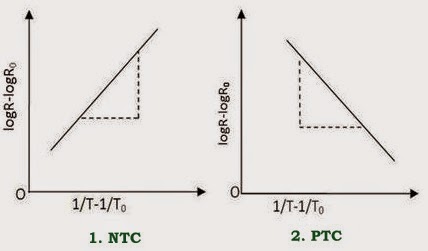
As just mentioned above, resistance increase with increase in temperature for PTC and resistance decrease with increase in temperature for NTC.
The thermistor exhibits a highly non-linear characteristic of resistance vs temperature.

PTC thermistors can be used as heating elements in small temperature controlled ovens. NTC thermistors can be used as inrush current limiting devices in power supply circuits. Inrush current refers to maximum, instantaneous input current drawn by an electrical device when first turned on. Thermistors are available in variety of sizes and shapes; smallest in size are the beads with a diameter of 0.15mm to 1.25mm.
There are two fundamental ways to change the temperature of thermistor internally or externally. The temperature of thermistor can be changed externally by changing the temperature of surrounding media and internally by self-heating resulting from a current flowing through the device.
The dependence of the resistance on temperature can be approximated by following equation,

Where,
R is the resistance of thermistor at the temperature T (in K)
R0 is the resistance at given temperature T0 (in K)
β is the material specific-constant
R0 is the resistance at given temperature T0 (in K)
β is the material specific-constant
The material specific-constant of a NTC thermistor is a measure of its resistance at one temperature compared to its resistance at a different temperature. Its value may be calculated by the formula shown below and is expressed in degrees Kelvin (°K).

Thermistor Applications:
- PTC thermistors were used as timers in the degaussing coil circuit of most CRT displays. A degaussing circuit using a PTC thermistor is simple, reliable (for its simplicity), and inexpensive.
- We can also use PTC thermistors as heater in automotive industry to provide additional heat inside cabin with diesel engine or to heat diesel in cold climatic conditions before engine injection.
- We can use PTC thermistors as current-limiting devices for circuit protection, as replacements for fuses.
- We can also use NTC thermistors to monitor the temperature of an incubator.
- Thermistors are also commonly used in modern digital thermostats and to monitor the temperature of battery packs while charging.
- We regularly use NTC thermistors in automotive applications.
- NTC thermistors are used in the Food Handling and Processing industry, especially for food storage systems and food preparation. Maintaining the correct temperature is critical to prevent food borne illness.
- NTC thermistors are used throughout the Consumer Appliance industry for measuring temperature. Toasters, coffee makers, refrigerators, freezers, hair dryers, etc. all rely on thermistors for proper temperature control.
- We can regularly use the Thermistors in the hot ends of 3D printers; they monitor the heat produced and allow the printer’s control circuitry to keep a constant temperature for melting the plastic filament.
- NTC thermistors are used as resistance thermometers in low-temperature measurements of the order of 10 K.
- NTC thermistors can be used as inrush-current limiting devices in power supply circuits.
Get an idea about the following concepts also:


